Project/RelayMatrix
Introduction
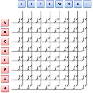
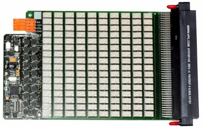
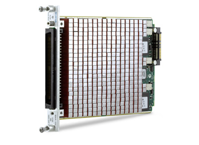
In professional test systems, there is often the need for switching. Power supplies, loads, and various measurement devices need to switch on or off, or be able to be chosen across multiple inputs or outputs on a test system. This is done by relays in most cases. Relays are fairly reliable, oppose little influence on the test system and have good conductivity in the "on" position, and also good isolation in the "off" position. As the complexity increases, the number of relays can also become very large. Purpose-built switching systems are efficient, but also less flexible. If you want maximum freedom, you will look for a system that can connect any input to any output. These kinds of systems have relays in a matrix configuration. For small signal types such as voltage measurements, a reed type relay is very compact, and a high density can be packed in a minimum of space. For switching larger currents, a more conventional type power relay is needed.
All of these relays must be switched at the right moment. Usually, there will be some sort of automated sequence system, controlling the progress of the task being performed. Scripting systems such as National Intrument's LabView or Keysight's VEE programs offer easy to understand graphical representation of a test sequence, with great flexibility. The test script systems communicates with equipment with a number of interfaces, varying from the ancient but still widely used IEEE488 parallel bus, to RS232, PCI variants, USB and Firewire buses and Ethernet connections. The common communication standard across all these interfaces is usually SCPI, the Standard Commands for Programmable Instruments. This is an human readable ASCII based set of commands, which is extensible and adaptable to a large number of instruments. Power supplies, vector analysers, multimeters and a host of other measuring and driving equipment can have SCPI support.
A relay matrix system is often an expensive piece of equipment, bound to a single vendor, and limited to a certain voltage or current. To find a suitable system, it can become neccesary to mix different types of relay matrix configurations. Because there of often the need for a compact system, small relays are used, which can be costly. Many thousands of dollars/euro's can be spent on a matrix system. But what if you could make a system yourself? Choose a cheap relay, buy them in bulk, and make your own system? This project proposes an open source, fairly cheap, modular matrix system with easy to obtain relays, and USB and/or Ethernet configuration ports. On top of this, and not offered very often, an integrated diagnosis system is offered, to keep track of the health of over a thousand relays. See statistics like activated time, number of activations, but also vital figures like contact resistance, can give insight on the condition of a relay. Welcome to project IO Dyne!
Everything you never wanted to know about relays
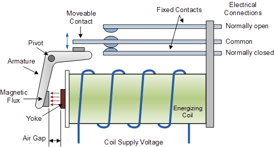
A relay is just like a regular switch. The difference between the two is where a switch is operated by a mechanical force (like a person), a relay can be operated by an electrical signal. A current is run through an electromagnet inside the relay, and this magnetism is used to operate the switch. There are a large number of switch configurations possible. A normally open (NO) contact can be closed by operating the relay, a normally closed (NC) contact can be opened. Also a combination of these two is possible with a dual throw (DT) or change over (CO) operation. All of these types of switches can be inside a relay 1 time (single pole or SP), or multiple times. If there are two switches inside, it is called a dual pole (DP), but more is certainly possible. The switch configuration is usually mentioned with a combination of these acronyms, like SPDT for a single change over configuration, or a 3PNO for a combination of 3 normally open switches.
Apart from the switch configuration, the coil to make the magnetic field can also vary a lot. DC as well as AC voltage operated coils are possible, and the coil voltage can be very small, like 3 volts, or very large, to over 380 volts. For DC coils, a built-in freewheel diode is possible. If this is the case, polarity must be observed when connecting the coil. Operation of the coil can also be latching. This means that, to switch over, a short period of energising the coil is only needed. This is also called a bistable relay. It can be done with one coil, which can be operated in opposite polarity, but also dual coil latching relays are possible, with each coil responsible for either making or breaking contacts. Non-latching or monostable relays typically have only one coil. As long as the coil is energized, the switch is activated, and without voltage on the coil, the relay is in its default state. Other properties can be a reed-type relay with a reed switch typically suited for small signals, safety relays, coaxial relays, or contact material designed for a specific type of signal.
A coil inside a relay is just like any other coil in terms of behavior. Coils usually conduct DC currents very well, and isolate fast changing AC currents. The coils resists changed by converting the electrical energy into magnetic energy. Of you keep running the DC current, the coil can no longer transfer energy, and the magnetic field stabilizes. It is this magnetic field that is used inside the relay to operate the switch contacts. But, if you no longer run current through the coil, it wants to resist this as well. It converts all magnetic energy back to electrical energy. The voltage generated by the relay coil can be very high and was often the cause of malfunction of the electronic component operating the coil. A diode opposite to the normal current flow is used to short-circuit this coil-generated voltage in order to keep semiconductors alive.
Apart from the coil, there is another property of the relay that is of our interest: the contacts. And in particular: the contact resistance. Like every mechanical connection, every switch contact has a certain resistance. Usually, this contact resistance is very low, in order to conduct current very well. But, when a relay ages, the contact resistance can become higher. The contact become corroded, and the ability to conduct electricity decreases. This effect can be minimized by the natural cleaning effect of tiny sparking happening when the contact is energized and a current is run through. Datasheets often specify the minimum amount of current needed for this, and depends on the material of the contacts, the contact surface, and many other parameters. The order of resistance in usually in the milli-ohms.
Resistance measuring
But how to measure these kinds of low resistances? You can no simply plug in your multimeter: it will read closely to 0 ohms, but no milli-ohms. This is because the multimeter uses a tiny current to measure the resistance. For high resistors, this works very well, but it is not suited for very low values. When you apply a higher test current, other factors come into play like wire resistance, whcih can surpass the value you want to measure many times over. Fortunately, there is a way to measure low resistance values accurately. 4-wire measurements!
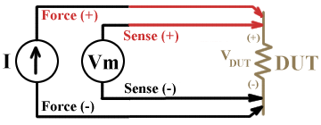
The principle of a 4 wire resistance measurement is quite clever: each terminal of the resistor has 2 wires connecting to them: One current bearing wire, and 1 voltage measuring wire. On the current wires, a constant known current is applied. Like 1 amps. The voltage drop across these terminals will be significant, due to the current running over them. If we would want to apply Ohm's law, measuring voltage over these wires, the value would be way off. Just like the multimeter would be. Fortunately, we do have a second set of wires connected to our resistor. These we use to measure the voltage! Because for voltage measuring, we have to use near-zero current, the voltage drop is negligible. This means we can accurately determine the voltage across our very low value resistor. With Ohm's law at our hand, we can tell what value our contact resistance is!
Controlling the hurdle
So now that we have a whole lot of relays, how do we control all of those? If you want to power a relay from, let's say a microcontroller, you could use a transistor. But what if you wanted to drive a whole lot of relays? Simply connecting then all to our microcontroller with a lot of transistors would result in a very large and expensive controller, and a whole lot of wires which will result in a difficult to produce and expensive circuit board. For our conveniece, there is a thing named a SIPO register. This register is a type of shift regsiter which accepts a number of values in a serian manner, and can apply those values to a set of parallel outputs. Often, such regsiters have cascading capabilities with an additional serial out port. A popular 74HC595 is a good example of such a shift register.
One major disadvantage of the 595 register is its output driving capability. It simply lacks the power to drive our relays. The output is of TTL level. 5V, about 20mA, simply isn't enough to drive relays. A suitable relays driver would be an Allegro ULN type darlington driver, like the ULN2803. It takes the TTL level signaals, and it can perfectly drive relays. It even has integrated freewheel protection diodes for driving inductive loads, like our relays are. The register-driver pair is a very commonly used solution for connection a large number of relays to a microcontroller, but in our high-density demands, it would result in a large circuit board because we have to use both a register and a driver for 8 relays. For 1024 relays, this means 256 IC's just for the relays! Apart from the number, the ULN2803 is only available in DIP and SO wide package. Not ideal for a high density matrix.
There are several purpose-built chips that provide a solution for this problem. For example, the MAX4820 from Maxim integrated. This is a SIPO relay driver, just like we need! It can be cascaded, can be supplied from 3.3V or 5V, has space-saving packages for high density solutions. One drawback is the price. It is expensive! Our final implementation uses the TPIC6C595 from Texas Instruments. It is available in a TSSOP package, which is reasonably small, and can drive 8 relays directly from a serial input. 8 of these are daisy-chained to control 64 relays, from a single microcontroller.
One level up
The next step is to control the relays boards. If we have 64 relays on a board, and 1024 relays in total, we would need 16 relays boards. All of these must be interconnected, and supplied with power. To maximize flexibility, a minimum of interconnections would be most beneficial. We can serialize data again like we did with the relay drivers, but a break in the chain would mean a breakdown of the entire system. Also, because of the distance that need to be covered, there would be a speed penalty, and signal integrity issues. We would need to look at a solution of a serial bus, which is kind of fast, and can handle cross-PCB distances with as little signal degradation as possible.
The automotive industry has a turn-key solution: The Local Interconnect Network or LIN bus. At the base of the LIN bus is a serial interface, and a bus master. It talks to all the connected slaves with an addressing protocol, and negotiates speed with a learning sequence. It handles noise and other interfering influences very well, and has only 1 connecting wire. Microchip has a whole range of microcontrollers supporting the LIN bus, as well as interface chips for level conversion.
Central command
The bus master for the LIN bus controls all relay boards, and is the central command center for all things relay related. So what else can we implement? How about the resistance measurement? As mentioned, we need two things for this. The first one being a constant current source. 1 amps would be sufficient to accurately measure milli-ohms. We only need a chip to generate exactly 1 amps. The most obvious way is to use a regulator. Where voltage regulators can be very precise, it can be hard to obtain a precision 1 amp current source. Ohms law to the rescue! If we can make a voltage source adjusted to 1.25 volt, and run it across a 1.25 Ohms resistor, we have our 1 amp current!
A Linear Technology LTC6655 precision voltage reference source is used. To drive the current, we need a driving transistor, for example a Fairchild NDT3055. In a DPAK housing, it can handle up to 12A, which is more than enough for our application. As a feedback buffer, Burr Brown's OPA376 is used because it has a very small offset voltage. Alltogether, this should generate an accurate 1 amps of current for measuring resistance.
The other thing for determining contact resistance is the voltage measurement. A differential voltage measurement would be preferred, because we want to look at the voltage drop across the switch contact. Again, Burr Brown offers very precise instrumentation differential amplifiers, like the INA122. With just 1 external resistor, we can set the amplification of the voltage. This output voltage can then be converted to a digital value by means of a Microchip MCP3421. 18 bits of resolution ensures a high level of density in our measured value, and a serial output simplifies PCB layout.
